A complete Video Guide to make this Circuit
Components Required
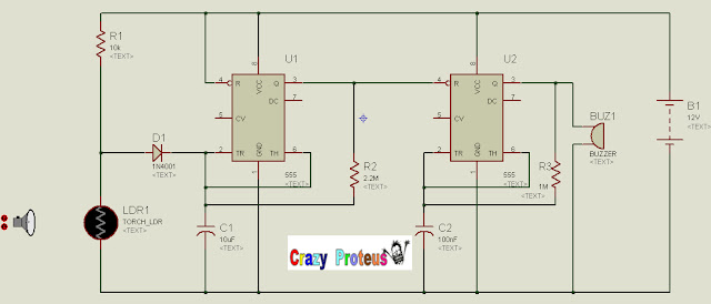
Diagram Taken From Internet To simulate the Circuit On Proteus:
Steps To Make the Circuit On Proteus:
Open Proteus professional.exe and pick components from pick devices.
Place all the components on the screen as shown in upper picture and give them Specify values according to the picture.
Connect one component with the other as per diagram.Click on one edge
Of the first component and then click on the others edge , a wire will connect Both.
Diagnose each component value and connection.
Play the circuit if circuit works then congrats J otherwise repeat step 4.
Take a print out of the circuit for your presentation
Diagram of My Circuit Simulated On Proteus:
- Battery
- 555 IC
- Resistors
- LDR
- Polarized capacitors
- Buzzer
How This Circuit Works:
In the circuit two 555 ics are used. Output of the first IC is connected to the input of the second IC.Resistors and capacitors are used to adjust the timing of the 555 timers.At the output of the 555 timer buzzer is connected.When the door of the fridge is closed ,there will be no light inside the fridge so the resistance of the LDR will be high and there will be charging of C1.When the door of the fridge opens ,there will be light inside the fridge which will decrease the resistance of the LDR which evantually stop the charging of the C1. C1 will start discharging and it will help the IC1 to oscillate and IC1 will oscillate IC2 and at the output we will listen the tone.
In the circuit two 555 ics are used. Output of the first IC is connected to the input of the second IC.Resistors and capacitors are used to adjust the timing of the 555 timers.At the output of the 555 timer buzzer is connected.When the door of the fridge is closed ,there will be no light inside the fridge so the resistance of the LDR will be high and there will be charging of C1.When the door of the fridge opens ,there will be light inside the fridge which will decrease the resistance of the LDR which evantually stop the charging of the C1. C1 will start discharging and it will help the IC1 to oscillate and IC1 will oscillate IC2 and at the output we will listen the tone.
Open Proteus professional.exe and pick components from pick devices.
Place all the components on the screen as shown in upper picture and give them Specify values according to the picture.
Connect one component with the other as per diagram.Click on one edge
Of the first component and then click on the others edge , a wire will connect Both.
Take a print out of the circuit for your presentation
Diagram of My Circuit Simulated On Proteus:
My Project File:
====> Click Here For Project File
Password: crazyproteus
Note : Proteus professional software is required for this circuit to open


i tried to simulate the circuit in ngspice but i am getting same output voltage for 2k and 2M ldr resistors...please help with this issue
thanks a lot.